How To With VMware
Deploying the vSphere Distributed Switch
The vSphere Distributed Switch extends the features and capabilities of virtual networks while simplifying provisioning and the ongoing process of configuration, monitoring, and management.
- By Vyenkatesh Deshpande
- 08/22/2012
The vSphere Distributed Switch extends the features and capabilities of virtual networks while simplifying provisioning and the ongoing process of configuration, monitoring, and management.
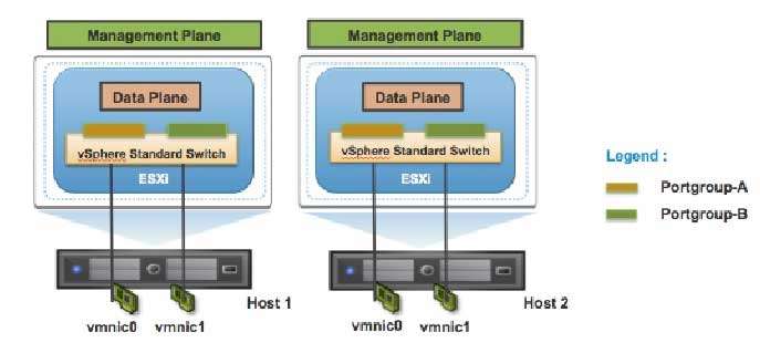
vSphere virtual switches can be broken into two logical sections (see Fig. 1). There is the data plane and the management plane. The data plane implements the actual packet switching, filtering, tagging, etc. The management plane allows administrators to configure different parameters of the data plane functionality. With the vSphere Standard Switch (VSS), the data plane and management plane are present on each standard switch. In this design, the administrator configures and maintains each VSS on an individual basis.
 |
|
Figure 1. vSphere virtual switches have two logical sections. The data plane is where actual packets switching, filtering and tagging is implemented; the management plane allows admins to configure the various functions of the data plane. (Click image to view larger version.) |
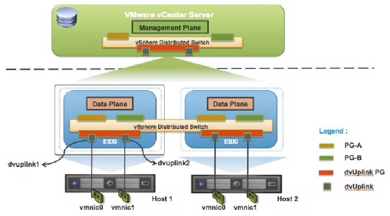
VDS treats the virtual network as an aggregated resource. Individual host-level virtual network parameters are abstracted as part of a single large VDS that spans multiple hosts at the Datacenter level (Fig. 2). In this design, the data plane remains local to each host, but the management plane is centralized with vCenter Server acting as the central control point for all parameter configurations and virtual network management. Each vCenter Server instance can support up to 128 VDSs and each VDS can connect up to 500 hosts.
 |
|
Figure 2. The data plane remains local to each host, but the management plane is centralized, with vCenter Server acting as the central control point for all parameter configurations. (Click image to view larger version.) |
Many of the concepts involved in configuring and managing a Standard Switch are carried forward with the VDS, with changes made to some of the virtual network parameters to support the abstraction.
Distributed Virtual Port Groups (DV Port Groups) are port groups associated with a VDS and specify configuration that is common across a group of distributed virtual ports. DV Port Groups also define how a connection is made through the VDS to the Network. Configuration parameters of DV port groups are similar to those available with Port Groups on Standard Switches with some additional options available for advanced features. The VLAN ID, traffic shaping parameters, port security, teaming and load balancing configuration, and other settings are configured here. Each VDS supports up to 10,000 static port groups.
Distributed Virtual Uplinks (dvUplinks) are a new concept introduced with VDS. dvUplinks provide a level of abstraction for the physical NICs (vmnics) on each host. NIC teaming, load balancing, and failover policies on DV Port Groups are applied to the dvUplinks and not to the vmnics on individual hosts. When a host gets added to the VDS, each vmnic on the host is mapped to a dvUplink, permitting teaming and failover consistency irrespective of vmnic assignments.
Deploying the vSphere Distributed Switch
This example shows how to migrate from an existing standard switch configuration to a vSphere Distributed Switch that spans across two hosts. VDS configuration can be accomplished in a number of ways, including:
- Using VDS wizards available in vCenter Server
- Using a combination of the vDS and Host profiles
- Using PowerCLI or vCLI commands
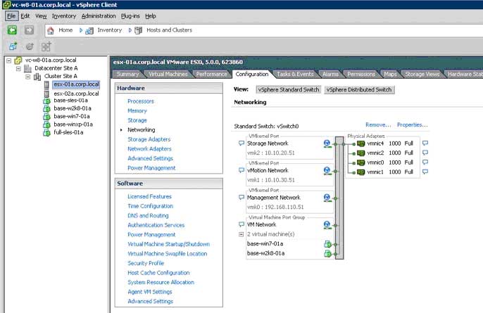
This post describes migrating from VSS to VDS using the vCenter Server wizard (Fig. 3).
The sample environment consists of the following components:
- Single vSphere Data Center
- 2) Two ESXi 5.0 Servers (esx-01a.corp.local and esx-02a.corp.local) in a cluster (Cluster Site A)
- 3) vSphere Standard Switch (VSS) configuration with the following port groups:
- VM Network
- Storage Network (VMkernel)
- vMotion Network (VMkernel)
- Management (VMkernel)
- 4) Five Virtual Machines with single vnic attachment to the VSS
 |
|
Figure 3. Migrating from VSS to VDS via the vCenter Server wizard. (Click image to view larger version.) |
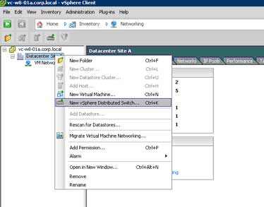
A VDS is created at the datacenter level in the vSphere environment. As shown in Fig. 4, at the Datacenter level, you can click on create VDS button to configure a new VDS:
 |
|
Figure 4. Click on create VDS button to configure a new VDS. (Click image to view larger version.) |
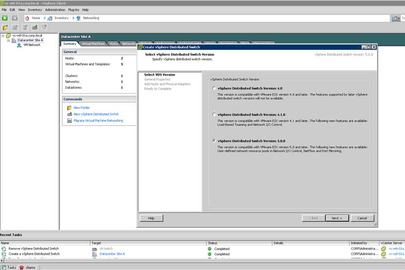
This will bring up a window (Fig. 5) to select the VDS version you wish to create. To enable advanced networking features in vSphere 5.0, select VDS version 5.0.0.
 |
|
Figure 5. Select the VDS version you wish to create. (Click image to view larger version.) |
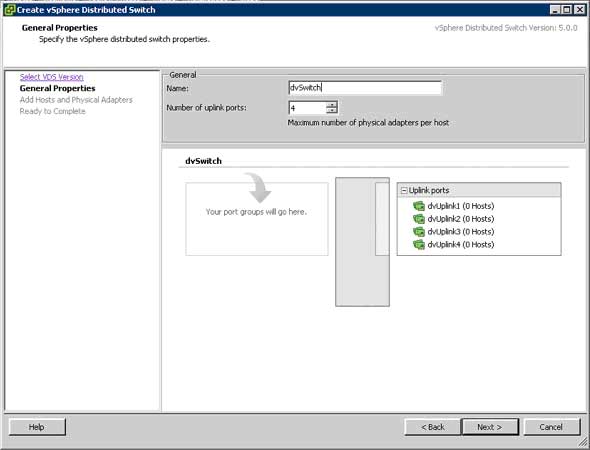
After creating the VDS, the networking panel will show a dvSwitch (the default name), and allow you to choose the number of uplinks to use for the VDS. You should have at least two uplinks configured for a VDS to allow for redundancy.
 |
|
Figure 6. Choose the number of uplinks to use for the VDS. (Click image to view larger version.) |
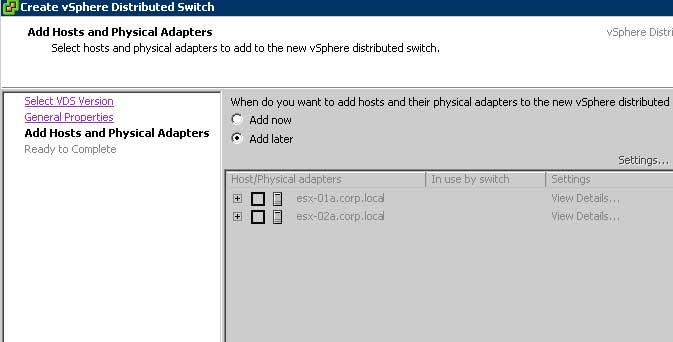
The next step in the wizard (Fig. 7) we will choose to add hosts to the VDS later.
 |
|
Figure 7. Add hosts to the VDS later. (Click image to view larger version.) |
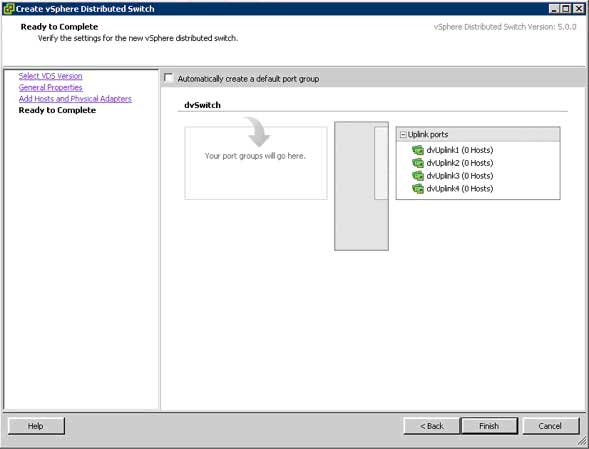
Next we will leave "Automatically create a default port group" unchecked (Fig. 8).
 |
|
Figure 8. Here, uncheck the Automatically reate a default port group box. (Click image to view larger version.) |
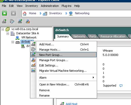
Next we will create Distributed Virtual Port Groups to match the requirements (Fig. 9). We start by right clicking on the new dvSwitch, and selecting "New Port Group."
 |
|
Figure 9. Create Distributed Virtual Port Groups. (Click image to view larger version.) |
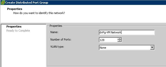
We will then name the new distributed port group. Here we choose dvPg-VM Network. We will also accept the default 128 ports and None for VLAN type. Depending on the configuration of the port groups on VSS, you should create a similar configuration on the distributed port group.
 |
|
Figure 10. Name the new distributed port group. (Click image to view larger version.) |
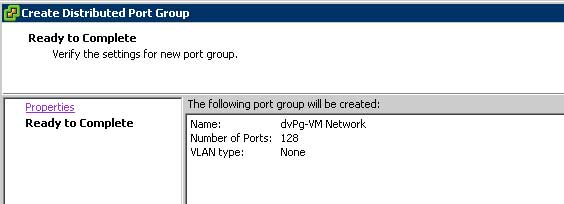
This brings you to the ready to complete screen.
 |
|
Figure 11. You're ready... (Click image to view larger version.) |
We would then repeat the exact same procedure for the remaining port groups. The end result is a VDS that is configured to connect virtual machines and ready for hosts to be added.
Add Host to vDS
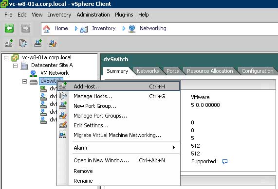
After creating a vSphere Distributed Switch and associated virtual network parameters such as distributed port groups, you can migrate hosts and physical adapters to this VDS. Start by right clicking on the new VDS and selecting Add Host.
 |
|
Figure 12. ... to migrate hosts and physical adapters to this VDS. (Click image to view larger version.) |
Next you will select the hosts you wish to migrate, along with the physical adapters per host that will be used for the VDS. In our example, we are assiging all four physical NICs per host to the VDS.
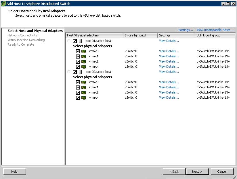 |
|
Figure 13. Select hosts to migrate. (Click image to view larger version.) |
The next step is to match the existing portgroups from the VSS to the distributed port groups on the VDS. The user first starts with the VMkernel ports (Fig. 14).
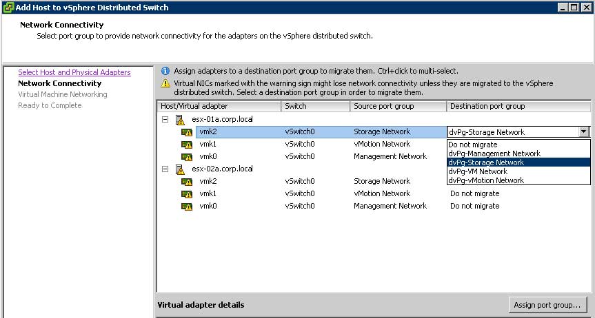 |
|
Figure 14. Match the existing portgroups from the VSS to the distributed port groups on the VDS. (Click image to view larger version.) |
Map each standard switch port group to the corresponding distributed port group.
Next the user will migrate virtual machine networking. As the sample configuration uses only one port group for virtual machine networking, this is as simple as assigning the correct port group to each virtual machine.
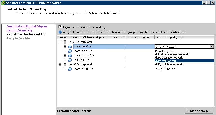 |
|
Figure 15. User will migrate virtual machine networking. (Click image to view larger version.) |
Once you have completed all of the portgroup mapping, you will come to the confirm screen. Validate all entries, and then click finish:
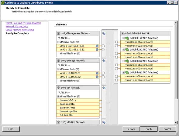 |
|
Figure 16. Migration, completed. (Click image to view larger version.) |
Once everything is complete, your VDS on a host should look similar to Fig. 17:
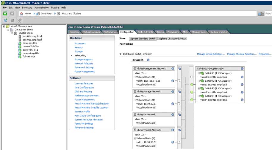 |
|
Figure 17. What your VDS host should look like, now. (Click image to view larger version.) |
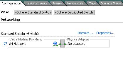
If we examine the vSphere standard switch on that host, you can see that all the adapters have been migrated to the VDS.
 |
|
Figure 18. All adapters have been migrated to the VDS; the evidence is in this screen. (Click image to view larger version.) |
The user can then decide to delete the VSS, or leave in place for a period of time until VDS operation has proved satisfactory.
We have covered the basics on the architectural differences between VSS and VDS. We also walked through the steps required to convert from a standard switch configuration to a vSphere distributed switch. For more details on the advanced features and to understand the different deployments with VDS please refer to the technical paper, "VMware vSphere Distributed Switch Best Practices," in the VMware Technical Resource Center.